Blank size calculation of a sheet metal complicated parts (considering K factor)
Sheet Metal blank size calculation :
Sheet metal working or steel working with various operations like bending or drawing etc. are complicated, requires practical working skills which is gained by long term working under proper supervision. However people having long life experience can do the work, but they are not able to explain the basic principle after the calculations. So i am going to explain what i have read in the books and in additional what i learned from the experiments.
Blank Length Calculation Formula (For CAD users) :
Since these days everyone is using CAD, so here i am going to share the basic blank calculation to enable students/freshers to make them reach close to exact value of the final product for CAD users, for instance see the below picture :

The Neutral axis (center line) shift towards the inner side due to compression occurs during Bending, the amount of shifting is mentioned by K-factor, which is roughly determined by the ratio of radius to the thickness. To calculate the length at the bend point follow the underneath rules :
R/T = 1, then offset the inner radius by 33% of thk.
R/T = 5, then offset the inner radius by 50% of thk. i.e the Neutral axis is in center
For more precise calculations :
The above formula is basic, however, for practical working conditions i have developed the under-given formula, which is derived from the experimental data for to use in real/practical applications of sheet metal bending, for first time right results.
Blank Length Calculation Formula (For Manual calculations) :
For users/technicians who are not cad literate, please follow the below formula :
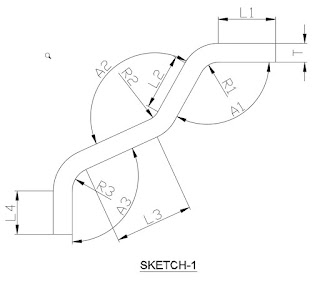
Length of Legs = L1, L2, L3, L4
Bend Radius = R1, R2, R3
Bend Angle = A1, A2, A3
Formula to calculate the Blank length = L + (R + K x T) x 𝛑A/180
For Example = (L1 + (R1 + K x T) x 𝛑A1/180) + (L2 + (R2 + K x T) x 𝛑A2/180) + (L3 + (R3 + K x T) x 𝛑A3/180) + L4
Let’s calculate the Length up to R1, take R1=10 and T=5 and corresponding K= 0.4
Total Length = (25 + (10 + 0.4 x 5) x (3.14×115)/180)) ⇸ 49mm
Extracting the blank shape of complicated parts :
In year 2006, with the help of training on Unigraphics CAD software, i get familiar with the automatic process of blank calculation, which was never so easy and convenient. The Meta form command works by meshing the mid surface of the Cad model with one fixed surface and unfold the selected surface in magical form. With the extracted surface you only have to fine tune with K-factor.
Nowadays it is called, One step calculation and here is the example : this advanced method is to use 3D cad (for complicated shapes) and FEA (One step form-ability analysis), as shown in the following pictures :


Method to be used in Siemens NX:

Define the input in each step :

Why correct blank size calculation plays important role :
The extracted blank shape is tentatively 80% correct, since it’s from mid surface (Neutral Axis) and bend allowance has to take care at the Radius according to the calculation mentioned in the above table and blank shape to be scaled accordingly.
Why correct Process design is mandatory for Final result :
Furthermore all holes to be pierced only after bending process by considering the positional accuracy, Since holes in blank may get deform/Oblong after bending and hole position may shift from the desired location, which should be therefore to be done after bending. The blank location in the bending die has a key role in maintaining the final dimensions.
If you want to learn the Metal forming simulation, read the book “Practical guide to forming simulation“
