Bending Force Calculation :
There are various ways to calculate the bending force of a sheet metal parts, most basic is to use the formula. Since it’s a basic and everyone should know about theory, however there may be some variations in results due to error in input values such as Tensile strength, coeff. of friction (not considered in formulas), press type (Mechanical or hydraulic) and other practical aspects which are not possible to measure. Therefore these force values to be taken as reference and sufficient factor of safety to be considered, minimum 20% to be added to select the final press. 100% correlation of formula and actual press force is impossible, even FEA softwares have certain limitations.
Bending in a V-die
The bending force (F) in V-bending is calculated using the formula:
F = (k × S × t2 × L) / (V × 9.81)
Where:
- F = Bending force (in tons)
- k = Bending constant (e.g., 1.33 for air bending)
- S = Ultimate tensile strength of the material (in MPa)
- t = Thickness of the sheet metal (in mm)
- L = Length of the bend (in mm)
- V = Opening width of the V-die (in mm), normally 6 x thickness
For a mild steel sheet with the following properties:
- Thickness (t): 2 mm
- Tensile strength (S): 400 MPa
- Bend length (L): 1000 mm
- V-die opening (V): 12 mm (calculated as 6 × t)
- Bending constant (k): 1.33 (air bending)
The bending force is calculated as:
F = (1.33 × 400 × 22 × 1000) / (12 × 9.81)
Final Result: The required bending force is 1.81 tons.
Fea software calculation given for co-relation
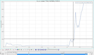
FEA force is 12753N = 1300 kfg (almost nearby the formula)
Bending in a U-die
Bending in a U-die, equipped with a spring-loaded pressure pad:
To calculate the bending force for U-bending, use the formula:
F = (k × S × t2 × L) / V
Where:
- k: Bending constant (e.g. 1.5~1.6 for U bending)
- S: 400 MPa (Tensile strength)
- t: 2 mm (Thickness)
- L: 1000 mm (Bend length)
- V: 12 mm (Die opening), normally 6 x thickness
F = (1.6 × 400 × 22 × 1000) / (12 × 9.81)
Final Result: The required U-bending force is approximately 2.17 tons.
Bending with bottoming (coining):
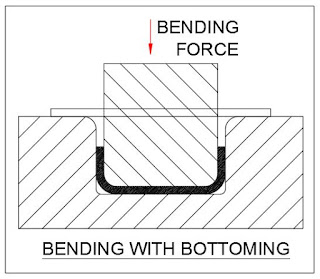
For bottoming, the bending force is calculated using:
F = (k × S × t2 × L) / V
Where:
- k: 1.8~2.0 (constant for bottoming)
- S: 400 MPa (tensile strength)
- t: 2 mm (thickness of sheet)
- L: 1000 mm (bend length)
- V: 6 mm (die opening), 3Xt
Substitute values into the formula:
F = (2.0 × 400 × 22 × 1000) / 6
Final Result: The required bending force for bottoming is 5.44 tons.
Wipe bending dies pressure calculation:
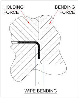
To calculate the bending force for wipe bending, use the formula:
F = (k × S × t2 × L)/V
Where:
- k: 1.5~2.5 (constant for Wiping)
- S: 400 MPa (tensile strength of the material)
- t: 2 mm (sheet thickness)
- L: 1000 mm (bend length)
- V: 12 mm (die opening), 6Xt
Substitute values into the formula:
F = (2.0 × 400 × 22 × 1000) / 12
Final Result: The required wipe bending force is approximately 2.72 tons. Extra 30% force to be added as a pressure pad force to prevent material slippage.
FORCE CALCULATION IN ROTARY BENDING
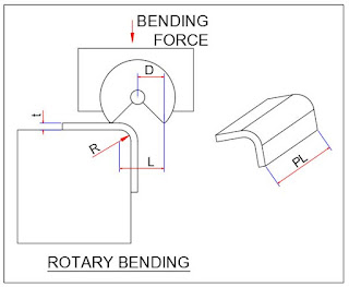
For rotary bending, the bending force is calculated using the formula:
F = (k × S × t2 × L) / V × R
Where:
- k: 1.0~1.2 (constant for rotary bending)
- S: 400 MPa (tensile strength of material)
- t: 2 mm (sheet thickness)
- L: 1000 mm (bend length)
- V: 12 mm (die opening), 6xt
F = (1.0 × 400 × 22 × 1000) / 12
Final Result: The required rotary bending force is approximately 1.36 tons.
FORCE CALCULATION FOR DRAW
Calculating the force required to draw sheet metal involves considering material properties, part geometry, and process parameters. Below is a step-by-step guide to estimating the drawing force.
Formula for Drawing Force
The drawing force (F) can be calculated using the following formula:
F = σ avg X A
where
F = Drawing force (in Newtons or pounds-force)
σ avg
= Average flow stress of the material (in Pascals or pounds per square inch)A = Cross-sectional area of the drawn part (in square meters or square inches)
Wh
Step-by-Step Calculation
Determine the Average Flow Stress (σ avg)
The average flow stress is the average stress required to deform the material during the drawing process. It can be estimated using the material’s tensile strength (σ ts) and yield strength (σ ys):σ avg = (σ ys +σ ts)/2
Where:
σ ts = Ultimate tensile strength of the material
σ ys = Yield strength of the material
Calculate the Cross-Sectional Area (A)
For a cylindrical cup, the cross-sectional area is calculated as:A = π × d × t
Where:
d = Diameter of the drawn part
t = Thickness of the sheet metal
Calculate the Drawing Force (F)
Multiply the average flow stress by the cross-sectional area:F = σ avg × A
Example Calculation
Let’s calculate the drawing force for a cylindrical cup with the following parameters:
- Material: Steel with σUTS = 400 MPa and σyield = 250 MPa
- Diameter of the cup (d): 50 mm
- Thickness of the sheet (t): 1 mm
Calculation Steps:
1. Calculate σavg:
σavg = (σyield + σUTS) / 2
σavg = (250 + 400) / 2 = 325 MPa
2. Calculate A:
A = π × d × t
A = π × 50 mm × 1 mm = 157.08 mm²
3. Calculate F:
F = σavg × A
F = 325 MPa × 157.08 mm² = 0.5 N
Final Result:
The estimated drawing force is approximately 0.5 tons Newtons.
Additional Considerations
Friction and Lubrication: Friction between the sheet metal and the die can increase the required force. Proper lubrication can help reduce it.
Die Geometry: Complex die shapes or sharper angles may require higher forces.
Blank Holder Force: In deep drawing, a blank holder is often used to prevent wrinkling. Its force must also be accounted for in the total calculation.
To learn more about Metal forming simulation, read the book “Practical guide to forming simulation”